Applying Practices from Instructor Systems to Designing Simulated Aircraft Avionics
Peer reviewed paper on simulated aircraft avionics built using .NET and WPF. Presented at I/ITSEC 2012 conference.
24 minute readDownload the published paper
Abstract
For the AT-6 Light Attack and Reconnaissance aircraft, the team at CAE USA approached the challenge of making its simulated cockpit instruments using process and technology refined by our instructor applications. Instructor applications are typically used in modeling and simulation to control the synthetic and virtual environments used to train students. This endeavor was different, as the Instructor Support group was used to design software for the pilots, not only the instructors.
This paper identifies a software architecture that can enable designers—those who are more visual and less software oriented—to gradually move into domain-specific software, like avionics. The development team embraced the principles of agile software engineering, used a newer .NET framework, and worked with a software architecture that has many similarities to ARINC 661, an avionics standard for designing cockpit displays.
Applying a process from a known area of design (instructor applications) to an unknown area of design (avionics) proved its mettle when we saw these technologies coalesce into a stable, demonstrable solution. Using FalconView as a backend map provider, a moving map was created for the avionics suite. This was possible by using the strengths inherent in Windows Presentation Foundation (WPF), a critical part of the overall design. This paper describes the process of developing those simulated displays. It also details how Instructor application developers worked with avionics experts to help achieve this task, the success of which rested heavily on using the Model-View-ViewModel software architecture.
The project was a procedural and technical success borne out of necessity. Having fewer avionics experts available for a project does not imply diminished results. The way instructor applications are designed (and engineered) can provide a window into a collaborative work environment—one that combines the skills of both analytic and artistic professionals—a global force.
About the Author
Matthew Crumley is an instructor support engineer at CAE USA, located in Tampa, Florida. He has seven years of experience working with M&S, predominantly using Microsoft .NET technologies. Mr. Crumley develops instructor interfaces for a wide variety of fixed and rotary wing simulators, and actively develops FalconView plug-in software. He is also a small business proprietor with an extensive background in web design and is currently experimenting with Apple iOS game development. Mr. Crumley received his bachelor's degree in computer engineering and an MBA from the University of Central Florida.
Matthew Crumley
CAE USA, Inc.
Tampa, Florida
The Right Seats
There's a global force of graphic designers and software developers waiting to make your organization prosper. The key, as Collins (2001) has identified, is getting the right people on the bus, then getting them in the right seat. It's a powerful idea and also applies to modeling and simulation (M&S).
Given the task of developing the desktop and unit task trainers for the HawkerBeech AT-6, CAE USA needed the right people in the right seats. In other words, it's about finding the right individual for the job.
A large part of the AT-6 development would be the avionics software that helps students fully utilize the cockpit. The Instructor Support group took up the task of creating the simulated avionics displays.
As this paper will explain, the right combination of process, personnel, and architecture were all necessary to design a fully functional suite of simulated avionics displays. Using Instructor Support designers proved valuable in terms of experience, but also the acknowledgement that all avionics software is not exclusive to one domain of expertise. Software patterns and practices can, and do, bring value when they are first acknowledged and then explored in new ways.
To capitalize on a global force of knowledge workers, the thought process of software managers is guided by two dissimilar, yet complementary concepts: software is both engineered, and designed. Our cockpit avionics displays blended these two concepts and shared software in common with instructor applications to quickly deliver working software.
Technology Timed Right
Our Instructor Support group has experience making traditional Windows applications with photo-real instrument repeaters. However, the AT-6 project was novel because its development was fully undertaken as R&D, which was a fortuitous chance to experiment with new code and new processes.
Our instructor applications were shifting to the newer Microsoft .NET frameworks, which also meant new tools. Windows Presentation Foundation (WPF), a part of the newer .NET framework, was chosen at roughly the same time our effort on AT-6 was starting. It became clear from experimental WPF applications that it had the design flexibility needed to do almost any kind of cockpit instrument. Those cockpit instruments would be the front line interface for student pilots while training on the AT-6.
The short project schedule imposed on development proved beneficial. In this case, the shift towards a more flexible graphical user interface (GUI) design paradigm was a great opportunity. Using WPF, a button can be styled like any type of cockpit display and—this is critical—it doesn't require an avionics engineer to write its code. We exploited what was clear: the framework enabled us to focus on avionics software and design markup individually. Instructor Support developers could, therefore, complement the effort typically undertaken only by Avionics engineers.
The team also went forward using agile principles from the Manifesto for Agile Software Development (Cohen, 2010, p. 14):
- Individuals and interactions (over processes and tools),
- Working software (over comprehensive documentation),
- Customer collaboration (over contract negotiation), and
- Responding to change (over following a plan).
The tight schedule left little time for a formal design process, which excluded the waterfall model. Although the waterfall model is still embraced for many projects, the overhead involved with a big design effort was not viewed as necessary or advantageous with no more than 10 people assigned to the project at a given time.
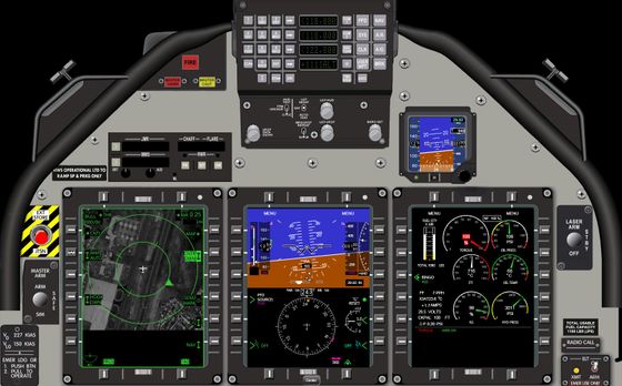
A Desktop Trainer (DTT) prototype was required and the schedule was set to three months for coding, integration, and test combined. This was the duration to achieve a working version of software that met the basics of a script, i.e. a rote scenario to exercise the abilities of the trainer. That meant it had to be working quickly. That also meant we had to use in-house experience and expertise to get the job done. Figure 1 shows the resulting DTT.
Using the Instructor Support group was also borne out of necessity. There were few avionics engineers available to do the entire suite of multi-function displays (MFDs) within the allotted schedule, which greatly reduced the pool of OpenGL expertise, the traditional backbone of avionics displays.
Performance on graphically intensive instructor applications showed us that WPF had the potential to be a worthy substitute. Access to cheap and effective tools made economic sense, and further simplified the decision to go forward with WPF.
Software Architecture
The simulated displays are very similar to creating an instructor application. As the following sections demonstrate, the known software architecture allowed development to advance with negligible accidental complexity.
Model-View-ViewModel
The arrival of Microsoft's .NET 3.0 framework in November 2006 also marked the introduction of WPF and a new programming pattern called Model-View-ViewModel (MVVM). Using MVVM is optional; however, it allows designers and software developers to create applications that utilize numerous time-saving features.
The idea of separating presentation from underlying business logic is not new. The Model-View-Controller (MVC) pattern has existed for years. The intent is the same with MVVM, yet its implementation rests heavily on data binding. One innovation behind WPF is the automated mechanism that allows a graphical object to receive updates from a data source (Data Binding Overview, 2012). Thus, creating software becomes more about solving the problem at hand, and less about the plumbing and infrastructure.
Patterns are harder to formalize when the release of new frameworks is so relentless, and MVVM is no exception. Although there is no standard that defines MVVM, its elements are typically described as follows.
Model
The Model processes and abstracts the lower level data that it receives. In effect, the model is the business logic that makes calculations and provides information to the GUI. The goal of its design should be to simplify data into a form that is flexible for the GUI and meaningful to the user. Depending upon the use of MVVM, this may not be the lowest level for domain or business logic. The model uses avionics data but further refines it to prepare it for the View.
View
The View is the visible user interface on the MFD—it's what the pilot sees. For the AT-6 we felt the granularity necessary to define a View should be the equivalent to an application window.
Using Microsoft's Extensible Application Markup Language (XAML) the window would be styled as a black rectangle and the adornments for the specific display, be it a Primary Flight Display (PFD) or the Engine Indicators and Crew Alerting System (EICAS), would become part of that View.
Figure 2 is a short example of XAML. This is the only markup required in the AT-6's MFD window to instantiate a moving map control.
<Fvw:WpfMapControl Width="330" Height="330"
    HeadingDeg="{Binding OwnshipHead}"
    LatitudeDeg="{Binding MapCenterLatDeg}"
    LongitudeDeg="{Binding MapCenterLonDeg}"
    IsMapVisible="{Binding IsMapEnabled}"
    Brightness="{Binding MapBrightness}"
    SelectedMapHash="{Binding MapHash}"
    MapZoom="{Binding MapZoom}"/>
Web developers who have used Smarty will find the preceding markup very comforting. Smarty is a templating engine used to separate web markup like HTML from the business logic, which is commonly implemented with PHP (Smarty Manual, 2012). A sample of Smarty markup is shown in Figure 3. There is minimal effort to learn the markup needed for WPF if the designer's background is in web development or even mobile apps, like Android. Android developers who design views are also accustomed to this XML-like markup. There seems to be a convergence of graphic design markup in this format.
<body bgcolor="{$smarty.config.bodyBgColor}">
    <table>
        <tr bgcolor="{$smarty.config.rowBgColor}">
            <td>First</td>
            <td>Last</td>
            <td>Address</td>
        </tr>
    </table>
</body>
ViewModel
The ViewModel often serves as a mediator which further translates and refines the Model's data for the View. It utilizes .NET data binding to allow the two layers to communicate with only loose coupling.
Instructor System Refinements to MVVM
The definition of the ViewModel left something to be desired. The problem with n-tier architectures is that sometimes n-tiers are too many for a small team to manage; the ViewModel is one of those tiers. It exposes properties to the View for data binding but the Model can serve the same purpose.
Our ViewModel object simply connects the View and Model together and decides their order of initialization and shutdown. Our ViewModel classes only vary slightly depending upon the application, so are reused frequently with little or no modification. This was the same for the MFDs and our instructor applications. We felt the value proposition of .NET data binding was already evident between the View and Model layers. In practice there appeared to be few benefits of adding another layer of abstraction to the software.
Because the ViewModel is used to control the pairing of the View and Model, it was simply a matter of composing the pairs we wanted and putting them into a central location – this is what we call the Controller.
Composition Over Inheritance
The controller is a useful architectural construct from the point of view of MVVM. If the ViewModel is there to loosely couple our View and Model, what's left to oversee the use of ViewModel objects?
Using a controller object acts as a clearinghouse of all ViewModel pairs, as shown in Figure 4. In this respect, it places greater value in object composition over inheritance. Designers and engineers can glance at one class and identify the pairing of View and Model.
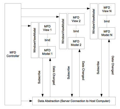
The Controller object, typically a singleton, creates the ViewModel objects and responds to commands to initialize or shut down each as needed (Figure 5).
For our instructor applications, the functional flow is easy to follow:
- Main entry point is called, which calls the
- Controller's Initialize method, which calls the
- ViewModel Initialize method associated with the primary window.

Windows are shown and closed through the life of the application via the Controller. The windows as we know them are altered so they have no border. They are opened and closed to simulate the different pages of an MFD display. The cockpit displays are like an instructor application but with different styling applied.
The Deep Model
The discussion up to this point has centered on the .NET application side but there's a critical software element without which none of the displays would function: the Deep Model.
This is terminology we, as Instructor Support developers, use to refer to the strict avionics-only software model. In many simulation environments there is a host computer that runs the real-time (60Hz) software load. The AT-6 is no different.
The Deep Model is written in a language chosen by the avionics engineers. It is exclusively in their domain and their control. This is software that's highly specific to the device which is being simulated. Indeed, the simulated displays are also device-specific but an artist or designer—someone given a set of available displays values—need not concern herself with the minutiae of how the hardware is being simulated.
Software Tools
The installed base of Windows PCs makes the platform an appealing target for all types of applications. Windows is running on embedded systems, desktops, phones, and most business have accepted the operating system as the de facto means to enable their workforce. Although our avionics displays are running on Microsoft Windows, the TCP communication layer allows the Deep Model to run on any operating system.
Assuming a project uses Windows exclusively, then for less than $900 the tool set to develop an avionics Model, View, and Deep Model is complete: Visual Studio 2010 Professional for code and Expression Studio 4 Ultimate for design. To build an AT-6 DTT, a team only needs these applications and reasonably equipped PCs. Proprietary or exotic OEM components are not required. Delivering value in M&S is much easier when the software tools are common and quickly understood by most of the project team.
MVVM and ARINC 661
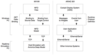
As Instructor Support developers, we're not familiar with standards associated with avionics, the equipment, or its detailed function. The Deep Model simulation is abstracted away for us into integer, floating point, Boolean, and character values. However, the driving business decision for using .NET and MVVM is familiarity. It's worth taking a diversion into an avionics-heavy architecture, ARINC 661 (2010), to see its notable similarities to MVVM.
The tool we used for the AT-6 displays, Microsoft Expression Blend, augments the role of a designer in utilizing a platform, but doesn't clutter the design markup with lots of domain knowledge. Should a designer be thoroughly concerned about the platform? The concern is whether tools for developing ARINC 661 systems will enable a flexible workforce, or play to the strengths a specific domain like avionics.
The review of ARINC 661 presented here is simply to confirm and not necessarily validate MVVM as a viable architecture for developing simulated cockpit displays. The impetus is to single out a pattern shared by a similar domain (human factors engineering) but with a very different implementation and platform.
Cockpit Display System
ARINC's Cockpit Display System (CDS) is analogous to the View of MVVM. It has the primitive elements of the visual display that together make up the windows, layers, and widgets. This is what the pilots see. Refer to Figure 6.
User Application
ARINC's User Application (UA) is analogous to the Model of MVVM and also to the Deep Model. Although UA code can be in any language, our separation of Model and Deep Model allows for similar decoupling of presentation and processing. ARINC doesn't impose many constraints on the UA other than its required use of the ARINC 661 runtime protocol.
Definition Files
Definition files for 661 displays are stored in XML format while MVVM utilizes WPF's Extensible Application Markup Language (XAML). Refer back to Figure 2 for an example of XAML markup.
Widgets
ARINC widgets are the visual elements used on the CDS. These are equivalent to controls in the .NET framework. WPF allows any control to have a unique appearance and even update that appearance dynamically at runtime. This is analogous to the ARINC 661 StyleSet. Where the two substantively break is in MVVM's flexibility to go beyond the cockpit display itself. For the AT-6's DTT, the entire cockpit area is simulated down to the buttons, switches, knobs, and other indicators as seen in Figure 1.
The specification for .NET-based controls is very loose with respect to WPF. Only events, properties, and fields defined by the controls are relevant. Thus, a .NET button can look exactly like an AT-6 circuit breaker when the correct XAML is applied.
A WPF Map Control
The FalconView map control provides a concrete example that WPF helped fulfill a critical part of modern glass cockpit displays. FalconView is the map application that is part of the Portable Flight Planning Software (PFPS) suite of applications used for mission planning. It was created by the Georgia Tech Research Institute for the U.S. Department of Defense. FalconView is in active development and, as of 2008, is also available to the public as open source software (FalconView, 2012).
Our Instructor Support group is accustomed to working with PFPS and specifically FalconView. Thus, it was a natural candidate for integrating with the MFDs as a moving map control.
FalconView primarily functions as a stand-alone application with a complete UI. However, its attraction lies with the ability to load plug-ins via Microsoft's Common Object Model (COM). We frequently use FalconView to provide tactical awareness to the instructors. We process the synthetic environment and overlay data on the map with threats and navigation data. These plug-in assemblies are completely written in .NET C#.
Problem
FalconView's strength is its ability to load different map data types, cache, scale, and project the imagery with great accuracy and precision. Notably, the UI can be separated from the map control. Integration with WPF implies two steps:
- Create a .NET control that uses the Graphics Device Interface (GDI) to render the imagery
- Use a built-in .NET control that wraps legacy controls so it will integrate with WPF.
The approach listed above worked but GDI was simply too slow. Additionally, the map rotation would cause the instance of the SQL server it uses for map data lookups to jump in CPU usage. When the aircraft yawed left or right, the moving map would lag with unimpressive results.
Solution
One of WPF's strength lies in its graphics backbone. Scaling, rotating, and translating are all possible and are frequently used to manipulate MFD objects. We utilized this strength as the starting point.
The goals of this new control were the avoidance of GDI and reduced impact on the SQL server. Utilizing the translation and rotation methods of WPF, the control simply exploited FalconView as a map data loader and provider.
There is moderate lag when requesting a tile of map data from FalconView. For example, the grid of 25 map squares shown in Figure 7 would only take two seconds to load. However, to avoid showing this tiling effect, our WPF map control caches the tiles well before they're displayed (shown in high contrast).
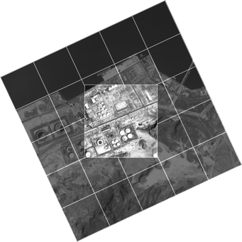
Moving map rotation is accomplished by rotating the set of tiles. Map translation is done similarly but the tiles are shifted up, down, left, or right so no additional tiles beyond the 25 are allocated.
All tiles are WPF Canvas objects, which are assigned the appropriate map image from a dedicated request thread.
Moving map brightness is the most trivial of all map objects to control. A WPF Rectangle object has the highest z-order and its opacity is adjusted based upon the desired brightness, where higher opacity results in a darker map.
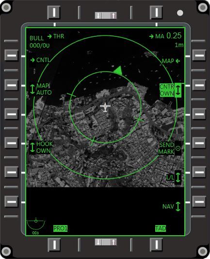
Minimal code is necessary to embed the control (refer back to Figure 2). The designer does not have to be concerned with the esoteric details of what the map control looks like–only what bindings to associate with its properties. The resulting MFD with a map display is shown in Figure 8.
As the next section will explain, knowledge about how those bindings are determined is a collaborative effort. Freedom from code does not imply ignorance of its limitations. The key is collaboration–mutual interest in the data.
Meeting in the Middle
All software processes should seek to enable better communication from inception to delivery. One way to enable communication is to structure the software in a way that ensures collaboration, reduces confusion, and therefore speeds development. Fortunately, there is a way to do this and we call it "meeting in the middle." It's an oasis where similar and dissimilar minds can meet. Boehm and Turner show that in pair programming scenarios, costs are 10-25% higher than using a single developer. However, development time is approximately 45% lower (as cited in McConnell, 2004, p. 480). Time, as mentioned earlier, was a concern on this project.
Industry Motivation
Tufte (2002) argues that for more sophisticated graphics, professional artists need more quantitative skills. This is logical but the process of integrating two distinct skill sets needs to begin somewhere.
Work by Tapp, Chartrand, and Campeau (2011) illustrate the goal of designing a cockpit display with artists and subject matter experts. They divide the work into view and model where the model, vis-à-vis this paper, appears to be the Deep Model.
Web design templating, which tried its best to hide business logic from the artist, gave way to general acceptance by the web community that software developers and visual designers cannot be blissfully ignorant of the other's thought process. The use of templating has been avoided by the most widely adopted blogging tool, WordPress, because the underlying web site code tends to creep outward and into design markup.
Improving expertise, tools, and software architecture broadly describe those areas that demand attention between designers and software developers. It's worth examining how our team addressed this collaboration vis-à-vis instructor applications and the AT-6 project.
Fostering Collaboration
We found that most C++ and even C software developers have found C# to be close enough to understand. All of our instructor applications are written in C# and the MFDs are no different. The expansive set of .NET classes usually befuddles avionics engineers new to .NET, rather than the language syntax itself. Commonly understood tools are important and using Microsoft Visual Studio, a familiar IDE, meant there was one less barrier to achieving productivity.
Developing an instructor application typically involves a lot of question/response with system engineers—domain experts—who understand the aircraft or synthetic environment. However, there's a bit of latitude for the designer when constructing a page for the instructor. Layout, formatting, and how a system is simplified to quickly execute a procedure is largely the designer's job and part customer feedback. For cockpit displays, this was not the case. We had to play to the strengths of both engineer and designer (see Figure 9). Using test pilots to validate the system was, in the case of the AT-6, critical in terms of how well the instruments were represented visually and functionally.
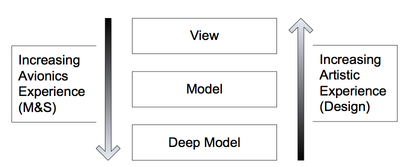
Our Instructor Support engineers have a good deal of software coding experience, but the key feature of this process is that gradations of expertise are built into the structure of the software. Maybe you have employees who want little to do with code but are brilliant graphics designers who can quickly draw MFD displays. They can design the View and gradually delve into more complex, domain-specific code starting with the Model. An n-tier architecture is advantageous in a scenario where there are a large number of specialized professionals working on one tier of a larger software project. However, the architecture should allow for those individuals to cooperate and expand their expertise, if they choose.
The Model is developed by the Avionics and Instructor Support teams. In fact, our source control records indicate multiple check-ins of the Model by the Avionics team, but predominantly by the Instructor Support team.
Because the Model is mostly a façade, or simplification of the Deep Model, it makes sense for the Avionics engineer to collaborate on its design. The Instructor Support engineer doesn't own the file, but is the primary developer of its capabilities – she understands what data is necessary to adequately supply the View with colors, positions, and other data that it needs to render a control. However, its development along with the avionics domain expert is critical.
Finding the middle ground is easier when there's an actual file in which to base the discussion. Thus, collaboration is an architectural necessity that allows both sides to have a shared stake in the outcome, yet acknowledges both sides have a specialized area of expertise.
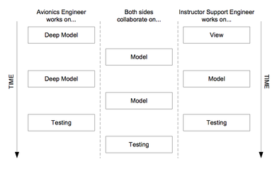
Our development process followed a cyclic but reliable pattern that gave Instructor and Avionics developer time to do domain specific work, but also focus on a common effort. Figure 10 shows one cycle, where the goal of the cycle is to produce working software.
Classes are commonly named so that both sides understand their purpose and can trace back where to find a control on a display. For example, to find the View associated with the EICASModel class, the developer need only search for the EICASWindow class. Logical naming conventions were another means to reduce confusion and allow developers and designers to write software and design visual elements that work together.
Results
After a couple development iterations we produced a functional AT-6 cockpit and MFDs that proved to us the technology (WPF), architecture (MVVM), and the process (agile) can produce results. Costs were kept low by using flexible tools: Microsoft Visual Studio and Expression Blend. Shortly after development started, it was decided the same technology and process were good enough to develop the AT-6's Heads-up Display (HUD). The HawkerBeech test pilots were convinced that the execution of the project was on the right track.
As the program reached a development plateau the trainer was stable enough to demonstrate at the 2011 Paris Air Show and subsequent trade shows, including I/ITSEC.
Areas of expertise such as FalconView and the Deep Model of avionics software are not common outside of the M&S industry. Finding the right people for these skills implies graphic design and software development experience is necessary but not sufficient. Establishing areas for these specialists to meet in the middle, with pair programming or other agile processes, can reduce the time needed to create working software.
The results presented in this paper are focused on a set of Microsoft products and the Windows platform, which could be a disadvantage to many organizations that prefer an alternative solution, i.e. the Linux OS. When designers and developers can choose the tools that work best, switch tools, and upgrade them, the platform becomes a lesser concern. The market has responded and there are many different non-Microsoft XAML designer applications similar to Expression Blend. Choices are out there.
The Future
The AT-6 DTT, as developed by Avionics and Instructor Support engineers and designers, represents the recreation of a real aircraft into a purely software construct. The question that should drive the 21st century of M&S, is how to use a growing population—a global force—for making better software. Does M&S simply iterate on existing software patterns, or can it formulate its own using a wide spectrum of knowledge workers?
According to the U.S. Bureau of Labor Statistics (2012) the estimated employment numbers from 2010 to 2020 for Graphic Designers will increase by 30.6% in the field of "Professional, scientific, and technical services." The increase for Software Developers is even more astounding at 52.2%. This means there will be ever more graphic designers ready to help distill the data-fueled M&S industry for years to come.
It's a challenge for management and an opportunity for the industry to shakeup traditional means of creating software. Shedding rigid definitions of what software tools are needed and what people and skills are required may balance the scales for M&S businesses to be equal parts design and engineering.
References
Boehm, B., & Turner, R. (2004). Balancing agility and discipline: A guide for the perplexed. Boston, MA: Addison-Wesley.
Cohen, G. (2010). Agile excellence for product managers. Cupertino, CA: Superstar Press.
Collins, J.C. (2001). Good to great: Why some companies make the leap…and others don't. New York, NY: HarperCollins Publishers.
McConnell, S. (2004). Code complete: A practical handbook of software construction (2nd ed.). Redmond, WA: Microsoft Press.
Tapp, M., Chartrand, S. & Campeau, J-F. (2011). Experiences in Leveraging M&S Expertise by Hiding Software Complexity. Proceedings from I/ITSEC 2011 Conference: Paper #11236.
Tufte, E.R. (2002). The visual display of quantitative information (2nd ed.). Cheshire, CT: Graphics Press.
"ARINC 661 Cockpit Display System Interfaces to User System" ARINC Specification 661-4. May 2010. ARINC, Inc. www.arinc.com. Data Binding Overview. (2012). Retrieved April 10, 2012 from http://msdn.microsoft.com/en-us/library/ms752347.aspx.
FalconView. (2012). Retrieved April 10, 2012 from http://www.falconview.org.
U.S. Bureau of Labor Statistics. (2012). Employment by industry, occupation, and percent distribution, 2010 and projected 2020. Standard Occupational Classification 15-1132 & 27-1024. Retrieved April 10, 2012 from http://www.bls.gov.
Smarty Manual. (2012). Retrieved April 10, 2012 from http://www.smarty.net/files/docs/manual-en-2.6.pdf